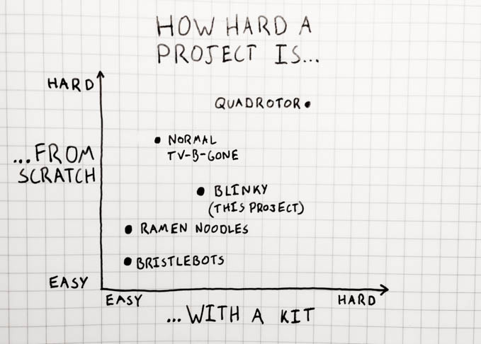
One of the first projects that I pursued to help teach me the basics of electronics and gizmo-making was a miniature TV-B-Gone. I liked it because it struck a good balance between not being overwhelming to build (it only uses about a dozen components) while still producing some fairly advanced functionality. When I was looking into starting up an electronics/hacker meetup at my school, it immediately came to mind as a great beginner project. I started looking into commercially available kits, and was put off by how they really don’t provide a good stepping stone from kit building into DIY projects.
One of the things that has always bothered me about normal “learn electronics” kits is that they’re typically very on-the-rails experiences that create a high barrier to entry to making your own stuff - it’s a big jump from soldering pre-packaged parts onto a labeled, professionally fabricated PCB to designing and ordering your own similarly-professional hardware. To re-create the Adafruit TV-B-Gone kit from scratch, you’d have to learn how to use EAGLE to edit schematics and design PCBs, then either learn to etch your own PCBs or navigate the confusing landscape of small-run PCB manufacturing services.
I’m attempting to bridge that gap with a “kit” that’s made entirely out of off the shelf parts, with no fancy custom-etched PCB or pre-programmed components. Just like a lot of my hobby designs, it’s first assembled on a breadboard before being soldered with perfboard. The idea is that a beginner could easily put it together and produce a reasonably polished end result, and then use the same tools & techniques from the kit to start designing their own projects. I’m putting together a number of kits to bring to my school’s “hack night” meetings for anyone interested in learning about electronics.
This post was made possible by a grant from the Lewis & Clark Center for Entreprenuership, was inspired in part by this instructable, and owes its existience to Lady Ada & Mitch Altman’s open-source TV-B-Gone code and schematics.
The rest of this post will walk you through building the kit, which I’ve named “Blinky”. In the end, you’ll have a micro-sized TV-B-Gone clone that will fit inside an Altoids smalls tin and can turn off nearly any TV at a range of 15-20 feet.
Parts & Tools
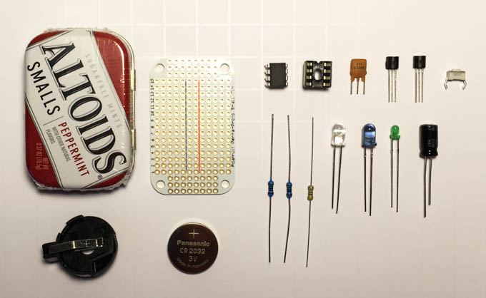
To build a Blinky, you will need the following parts:
- 1 × ATtiny85 Microcontroller (link)
- 1 × 8-Pin Component Socket (link)
- 1 × CR2032 3v Coin Battery (link)
- 1 × Coin Battery Holder (link)
- 1 × 8MHz Ceramic Resonator (link)
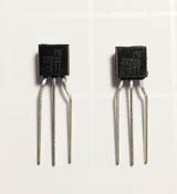
- 2 × PN2222 NPN Transistors (link)
- 1 × 220µF Capacitor (link)
- 1 × Green Indicator LED (link)
- 1 × Wide-Angle IR LED (link)
- 1 × Narrow-Beam IR LED (link)
- 1 × Slim Tactile Switch (link)
- 4 × 150Ω resistors (link)
- 2 × 47Ω resistor (link)
- 1 × Small Mint Tin Sized Prototype Board (link)
- 1 × Altoids Smalls Mint Tin (link)
I’ve put together a BOM so you can order all of the electronic components in one go here.
You will also need the following tools:
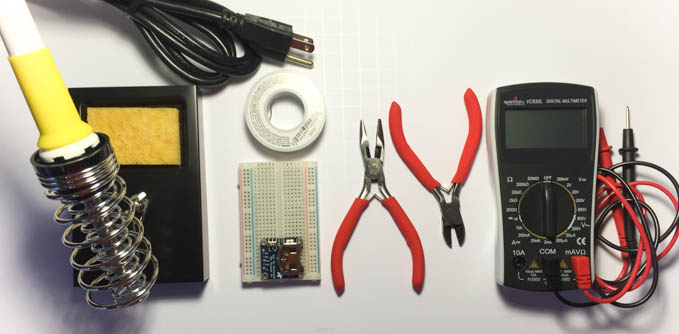
- Soldering Iron (with holder & wet sponge) (link, cheaper option)
- Solder (link - you can also use lead-free solder, but it makes it a bit tricker)
- Needle-Nosed Pliers (link, cheaper option)
- Flush Cutters (link, cheaper option)
- Multimeter (link, cheaper option)
- Breadboard (link)
- Assorted solid-core wire (22 gauge recommended)
- Coin Cell Breadboard Breakout (link)
- AVR Programmer (link)
- AVR ISP Breadboard Adapter Kit (link)
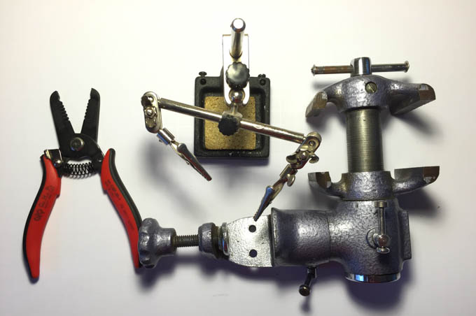
The following items are optional, but helpful:
Programming Part 1: Wiring
If you’re using a kit you got from me or at a Hack Night event, your ATtiny is pre-programmed. You can skip straight to the Building & Testing on a Breadboard section.
This project works by using a microcontroller to send out a whole bunch of TV “off” signals. However, the microcontroller you just bought is blank - it doesn’t have any code or TV “off” signals programmed into it yet. We’ll use the AVR programmer along with some open-source code to program the microcontroller to send out TV codes whenever it is reset.
The first step is to set up the circuit for programming. We’ll do this using a solderless breadboard. If you’ve never encountered a breadboard before, now would be a good time to review SparkFun’s excellent solderless breadboard tutorial. Go ahead, I’ll wait.
The AVR ISP programmer cable has six connections on it. VCC and GND are used to provide power to the chip being programmed. The other 4 are used while programming the chip. We’ll need to connect all six in order to set up our programmer. The pinout for these connectors can be found in Atmel AVR Application Note 042, and I’ve included it below. The Adafruit breakout we’re using also happens to have each pin labeled, which is nice.
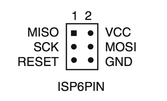 ISP 6-pin connector pinout
First, put the AVR programming adapter on the breadboard and connect the VCC and GND to the power rails of your breadboard. I like to keep my wiring as flush with the breadboard as possible - it helps with organization. Note the power jumpers at the bottom of the board - I often forget these and then get really confused when my circuit doesn’t work because one power rail isn’t connected to anything.
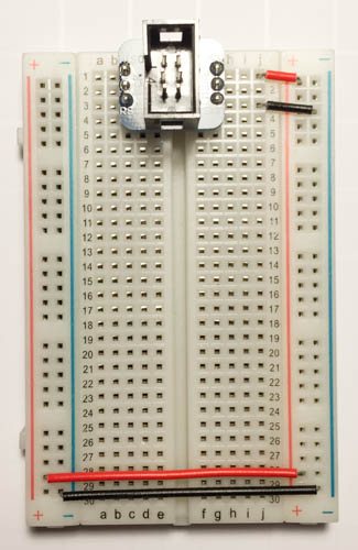 ISP power connections
Next, we’ll add the ATtiny85 chip. The pinout for this chip can be found in its datasheet. On the physical chip, the top left of the chip (pin 1) will be marked with a small dot. If you plug the chip in backwards, it can fry the chip, so be careful and pay attention to the dot!
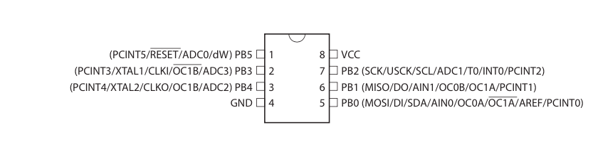 ATtiny85 pinout
To get the chip to fit in the breadboard, you’ll need to bend the leads a little bit. Use a table or other flat surface to gently bend the leads inward on each side:
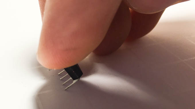 Gently bend the ATtiny leads
Plug the chip into the breadboard, paying careful attention to its polarity (the dot in the top left corner), and connect it to the power rails:
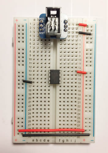 Chip with power connections
Next, connect the MISO, MOSI, SCK, and RESET signals to their respective pins on the chip:
 Chip with programmer signals
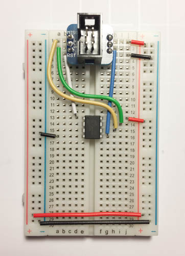
Finally, add the external resonator. This part is used to keep the chip’s timing accurate, and we’ll need it connected during programming. The resonator has three leads - the outer two need to be connected to the chip’s XTAL1 and XTAL2 pins and the inner lead needs to be connected to ground. The orientation of the resonator doesn’t matter. With a little bit of sneaky placement, you can accomplish this with a single jumper wire:
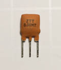 The resonator looks like this
 Resonator in place
Finally, plug the programmer into the breadboard. Make sure that the red wire is at the top (this shows the polarity of the programming cable).
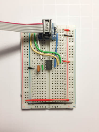 Ready to program
Programming Part 2: Software
Now that your chip is all wired up and ready to program, it’s time to get the programming environment setup on your computer. This will allow your computer to download instructions to the chip via the programmer.
The first thing you’ll need to do is install avrdude, an open-source utility for programming AVR chips. On OSX, I do this by installing homebrew, then running brew install avrdude in the terminal. Most Linux distributions also have avrdude available from their package managers. For Windows, you can follow this tutorial to install WinAVR which includes avrdude.
Once you’ve got avrdude installed, you should be able to run avrdude in your terminal and get a list of all the options that avrdude supports. If you get a “command not found” message instead, go back and troubleshoot/reinstall avrdude.
The next thing you’ll need is version 1.1b of the TV-B-Gone microcontroller software. Download it here. (I got it from Adafruit’s site).
Unzip the tvbgone11b.zip file you just downloaded somewhere convenient. Inside the directory there are a bunch of files, but the one we care about is tvbgone.hex. This is the compiled version of software, ready to be downloaded to the chip using AVRdude.
Now we’ll be actually programming the board. Make sure that your programmer is plugged into your computer and that your breadboard is plugged into your programmer in the correct orientation with the red wire at the top. Then run this command in your terminal:
avrdude -c usbtiny -p attiny85 -U lfuse:w:0xfe:m -U hfuse:w:0xdf:m -U efuse:w:0xff:m
This sets the chip to use the external oscillator for timing. You should see a line of output that looks like this:
avrdude: safemode: Fuses OK (E:FF, H:DF, L:FE)
Next, flash the tvbgone.hex file by running this command (make sure to change /Users/qrohlf/Downloads/ to wherever you extracted the folder to):
avrdude -B 1 -c usbtiny -p attiny85 -U flash:w:/Users/qrohlf/Downloads/tvbgone11b/tvbgone.hex
You should see some progress bars and finally some lines of output that look like this:
avrdude: verifying ...
avrdude: 8188 bytes of flash verified
If you see that, you’ve successfully programmed your ATtiny85 with the TV-B-Gone software and you’re ready to start building the TV-B-Gone circuit!
Building & Testing on a Breadboard
Now it’s time to wire up our TV-killer circuit. Circuits often come in the form of schematics. A circuit schematic is basically a map of how each part in a circuit gets connected together. Just like street maps, they’re a simplified version of reality, and usually don’t look much like the physical circuit at all. Here’s the schematic for the circuit we’re going to build:
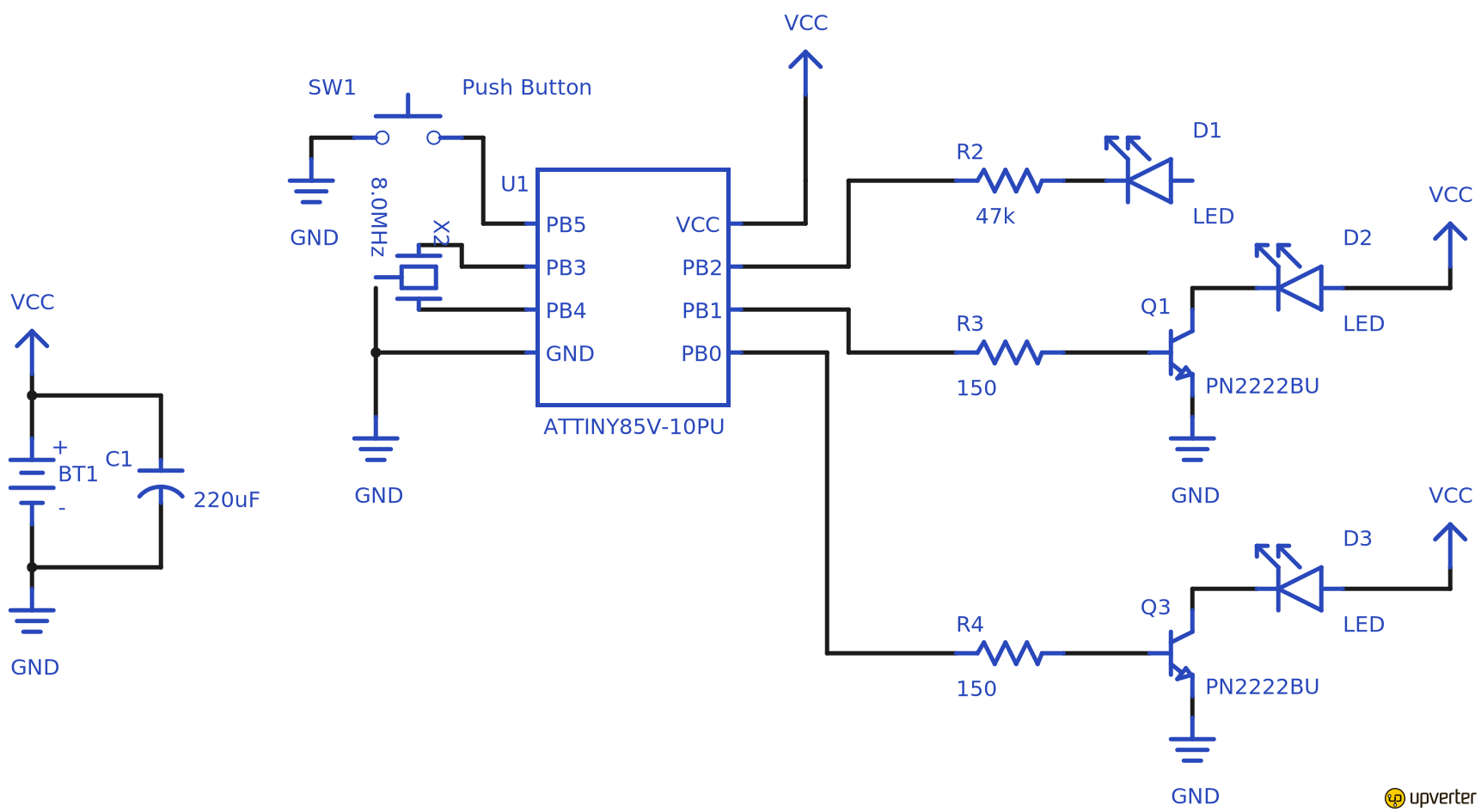 The schematic. Click for a larger image.
If you don’t understand it right now, don’t worry - this page will walk you through building it a step at a time.
We’ll be building this circuit on a breadboard first to test it out, then transferring the working design to a prototype PCB. If you skipped the programming section and haven’t used a breadboard before, take a moment to read this solderless breadboard tutorial.
If you’re continuing from the programming section, remove the ISP header and all of the wires coming from it, leaving only the ATtiny85, power connections, and oscillator. If you skipped the programming section, follow the instructions above to plug the chip into the breadboard and wire it up to the power rails and oscillator. Ignore the MISO, MOSI, SCK, and RESET wires. You should end up with something that looks like this, with pins 4 and 8 connected to power and pins 2 and 3 connected to the ceramic oscillator:
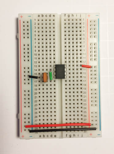 Basic connections
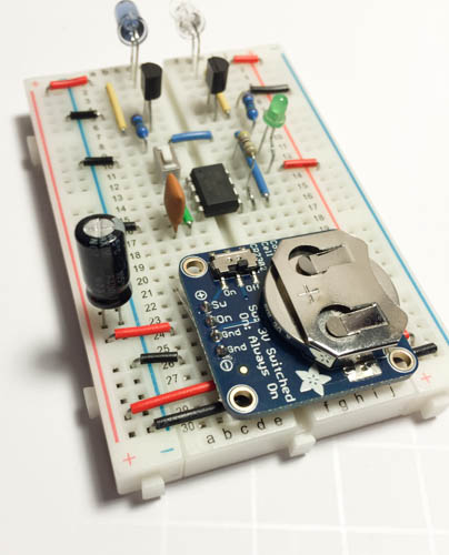
Next, add the battery. Slot the CR2032 coin battery into the breadboard coin cell breakout and plug it in at the bottom of the breadboard. Make sure the switch on the breakout is in the “off” position and wire the pins labeled “Gnd” and “Sw” to the ground and positive power rails on the breadboard:
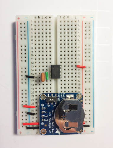 When the battery breakout is switched on, the battery’s positive and ground terminals will be connected to breadboard power rails.
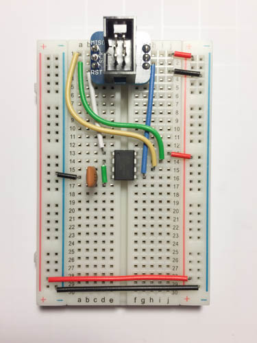
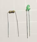
The circuit we are making uses a small green LED to indicate when it’s sending out TV codes. Because our circuit is running at 3v and the LED is designed for 2.5v, we’ll use a small 47Ω resistor (the one with the yellow-purple-black-gold band pattern) to step the power down (the Ω symbol means “Ohm”, a unit used to measure electrical resistance). If you’re interested in learning about the calculation I used to get this value, Sparkfun has a pretty good tutorial about LEDs and Ohm’s law. LEDs have two leads - one longer and one shorter. For an LED to light up, the shorter negative lead needs to be connected to ground, and the longer positive lead needs to be connected to the positive terminal of the battery.
We’ll connect the LED to pin 7 on our microcontroller, since that’s where the code we programmed it with expects the indicator LED to be connected. As a reminder, here’s the pinout for our microcontroller:
ATtiny85 pinout
When the microcontroller wants to light up the LED, it will connect pin 7 to ground, so we’ll connect the negative lead of the led to the pin and the positive lead to the positive power rail. The resistor we’re using can either go between the negative lead and the microcontroller, or between the positive lead and the power rail. Since the schematic shows it between the negative lead and the microcontroller, that’s where I’m going to put it.
 LED and resistor
To make things a bit more breadboard-friendly, I like to put a kink in the positive lead of LEDs with needle-nose pliers, then trim the leads so they’re about a centimeter long. This makes the components sit closer to the breadboard, keeping them out of the way while I’m working with other parts of the circuit.
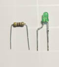 Trimmed leads
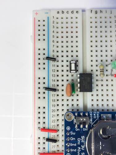
Here’s the breadboard with the LED and resistor added. Notice how I’ve re-used the same row that the chip’s positive power pin is on to power the LED - this has the same effect as wiring the LED’s positive pin to power separately would have, but it uses less space on the breadboard and keeps things a little bit tidier.
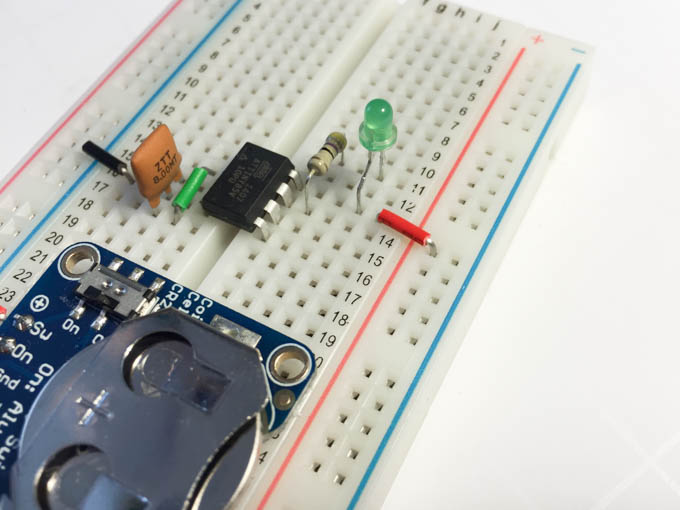 Circuit with indicator LED
Next, we’ll add the reset switch. This will go between the reset pin (pin 1) on the microcontroller and ground. When it’s pressed, the microcontroller will reset and start spitting out TV codes. These switches come with kinked leads - it helps to flatten them out with pliers before trying to plug the switch into the breadboard. Here’s what the circuit looks like with the switch installed on pin 1 of the microcontroller and connected to ground:
 Circuit with switch
We are now ready to do a basic test of the circuit! Double-check that the ATtiny is plugged in in the correct orientation (with the dot in the upper left corner) and switch on the power from the battery. Then press the switch (just press it, don’t hold it down). If you’ve wired everything correctly, the green indicator LED should start to blink. This means that the microcontroller is ready to send out codes!
If you don’t see the indicator LED blinking, double check all of your connections and make sure your battery isn’t dead and that it’s connected properly by checking the voltage on your breadboard’s power rails with your multimeter.
Once you’ve verified that your circuit works by getting the indicator LED to blink when the reset button is clicked, it’s time to add the infrared transmitter. This part of the circuit will send out powerful infrared signals based on input from the microcontroller, turning off any TV nearby by cycling through a bunch of different TV manufacturer on/off codes.
The actual infrared emitters are LEDs like the one we just installed as an indicator light. However, these LEDs emit light in the infrared part of the spectrum that TV remotes use (940nm). They’re also a lot more powerful, and unlike the little green LED our microcontroller can’t actually handle switching all of the power that they need to activate. Instead, we’ll be using the microcontroller to control another more powerful switch called a transistor.
 Transistors. I’ve bent the leads with pliers to help them fit in the breadboard.
Our transistor has three pins, the emitter, the base, and the collector. Like LEDs, the direction of power matters to a transistor. We’re going to connect the negative lead of the infrared LED to the collector of the transistor. The transistor base will be connected to the microcontroller, and the emitter will be connected to ground. When the microcontroller tells the transistor to “turn on” by supplying voltage to the base, the transistor will act like a switch and conduct electricity between the collector and emitter. This lets us control a lot more power than we could with just the microcontroller alone.
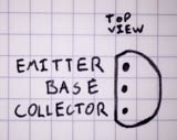 PN2222 transistor pinout
Pins 5 & 6 on the microcontroller will be controlling our transistors. Connect both pins together with a small wire jumper. Put the transistors in the breadboard and connect each emitter to ground and use a 150Ω resistor to connect each base to pin 6 on the microcontroller. (The resistor performs a similar function to the resistor on the LED, limiting how much power the transistors draw.)
 Transistor wiring
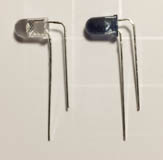
The final step is to wire up our infrared LEDs to our transistors. We want our LEDs to point forwards so we don’t have to hold our device sideways to point it at a TV. Take your pliers and bend the long (positive) lead of both IR LEDs straight down. Then bend the shorter (negative) lead at a slightly farther distance, so that it parallels the positive lead with about an 0.1” gap between the two leads.
 lead-bending is an art
Make a mental note which lead is which and cut the leads even so that you can install the LEDs into the breadboard. Leave the leads fairly long, since this will make soldering easier later on. Connect the positive leads to the positive power rail on the breadboard, and the negative leads to the transistor collectors.
 LED wiring
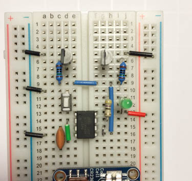
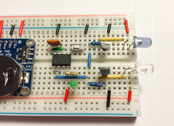
Finally, add the capacitor across the power rails. This will help provide consistent power to the LEDs while they’re pulsing at very fast rates. The capacitor has a positive and a negative side, the negative side has a shorter lead and a stripe down it. Connect the negative lead of the capacitor to the negative side of the power rails and the positive side to positive. Again, leave the leads fairly long to help with soldering later.
 Power capacitor
You should now be ready to test out your TV-killing “Blinky” gizmo. Find a handy nearby TV (it’s got to be the kind of TV that has a remote - a computer monitor or projector won’t work), make sure your battery switch is turned on, point the IR LEDs at the TV, and press the button. Within sixty seconds or so, you should see the TV turn off! When it does, you’re ready to go on to the next step.
If you’re having trouble getting your device to work, you can check and see if your IR LEDs are firing with a digital camera. Point the camera at the IR LEDs and watch the screen while activating the device. You should see rapid-fire pulses of light from the IR LEDS in the camera screen. If you’re not seeing these, go back and double-check your wiring. (Note that this won’t work with newer iPhones or any other camera that has an IR filter.)
Final Assembly
Coming soon!